Using val3dity
Note
val3dity is a command-line program only, there is no graphical interface. Alternatively, you can use the web application.
How to run val3dity?
To execute val3dity and see its options:
$ val3dity --help
To validate all the 3D primitives in a CityJSON file and see a summary output:
$ val3dity my3dcity.json
To validate all the 3D primitives in a CityGML file and get a HTML report, provide the path to the folder (eg /report_dir) that will contain the report report.html:
$ val3dity -r /report_dir input.gml
To validate all the 3D primitives in a CityGML file and get a JSON report:
$ val3dity --report_json report.json input.gml
To validate each 3D primitive in input.json, and use a tolerance for testing the planarity of the surface of 20cm:
$ val3dity --planarity_d2p_tol 0.2 input.json
To validate an OBJ file and verify whether the 3D primitives from a Solid (this is the default):
$ val3dity input.obj
The same file could be validated as a MultiSurface, ie each of its surface are validated independently
$ val3dity -p MultiSurface input.obj
Accepted input
val3dity accepts as input:
For CityGML/CityJSON files, all the City Objects (eg Building or Bridge) are processed and their 3D primitives are validated.
The 3D primitives are bundled under their City Objects in the report.
If your CityGML/CityJSON contains Buildings with one or more BuildingParts, val3dity will perform an extra validation: it will ensure that the 3D primitives do not overlap (technically that the interior of each BuildingPart does not intersect with the interior of any other part of the Building).
If there is one or more intersections, then 601 – BUILDINGPARTS_OVERLAP will be reported.
For GML files, the file is simply scanned for the 3D primitives and validates these according to the rules in ISO19107, all the rest is ignored.
For OBJ and OFF files, each primitive will be validated according to the ISO19107 rules. One must specify how the primitives should be validated (MultiSurface, CompositeSurface, or Solid).
In an OBJ file, if there is more than one object (lines starting with “o”, eg o myobject), each will be validated individually.
Observe that OBJ files have no mechanism to define inner shells, and thus a solid will be formed by only its exterior shell.
Validating one primitive in an OBJ as a MultiSurface (-p MultiSurface option) will individually validate each surface according to the ISO19107 rules, without ensuring that they form a 2-manifold.
If your OBJ contains triangles only (often the case), then using the option -p MultiSurface is rather meaningless since most likely all your triangles are valid. Validation could however catch cases where triangles are collapsed to a line/point.
Validating it as a solid verifies whether the primitive is a 2-manifold, ie whether it is closed/watertight and whether all normals are pointing outwards.
How are 3D primitives validated?
All primitives are validated hierarchically, for instance:
- the lower-dimensionality primitives (the polygons) are validated by projecting them to a 2D plane (obtained with least-square adjustment) and using GEOS;
- then these are assembled into shells/surfaces and their validity is analysed, as they must be watertight, no self-intersections, orientation of the normals must be consistent and pointing outwards, etc;
- then the
Solidsare validated- finally, for
CompositeSolidsthe interactions between theSolidsare analysed.
This means that if one polygon of a Solid is not valid, the validator will report that error but will not continue the validation (to avoid “cascading” errors).
The formal definitions of the 3D primitives, along with explanations, are given in Definitions.

Options for the validation
-h, --help
--geom_is_sem_surfaces
--overlap_tol
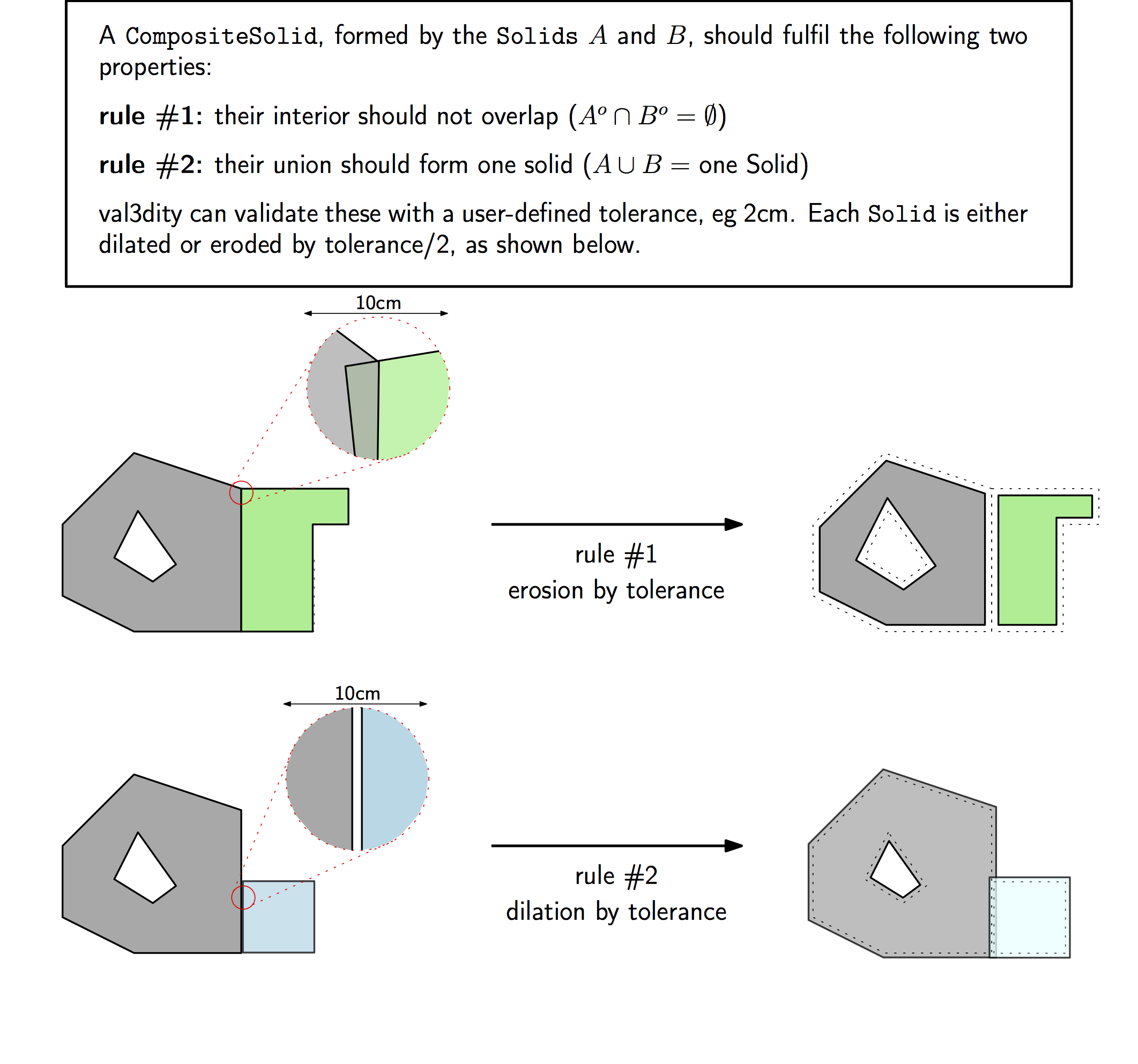
CompositeSolids and BuildingPartsThe maximum allowed distance for overlaps. Helps to validate the topological relationship between Solids forming a CompositeSolid or the BuildingParts of a building.
The tolerance --overlap_tol 0.05 means that each of the solids is given a 0.05unit fuzzy boundary (thus 5cm if meters are the unit of the input), and thus this is considered when validating. 0.0unit means that the original boundaries are used.
Using an overlap tolerance significantly reduces the speed of the validator, because rather complex geometric operations are performed.
--planarity_d2p_tol
The distance between every point forming a surface and a plane must be less than --planarity_d2p_tol (eg 1cm, which is the default).
This plane is fitted with least-square adjustment, and the distance between each of the point to the plane is calculated.
If this distance is larger than the defined value, then 203 – NON_PLANAR_POLYGON_DISTANCE_PLANE is reported. Read more at 203 – NON_PLANAR_POLYGON_DISTANCE_PLANE.
Note
Planarity is defined with two tolerances: --planarity_d2p_tol and --planarity_n_tol.
--planarity_n_tol
Helps to detect small folds in a surface. --planarity_n_tol refers to the normal of each triangle after the surface has been triangulated. If the triangle normals deviate from each other more than the given tolerance, then error 204 – NON_PLANAR_POLYGON_NORMALS_DEVIATION is reported. Read more at 204 – NON_PLANAR_POLYGON_NORMALS_DEVIATION.
Note
Planarity is defined with two tolerances: --planarity_d2p_tol and --planarity_n_tol.
-p, --primitive
Solid, CompositeSurface, MultiSurface.-r, --report
/report_dir) is required. This directory will contain report.html together with the required files to render it. Open it in a web browser.--report_json
--snap_tol
Geometries modelled in GML store amazingly very little topological relationships. A cube is for instance represented with 6 surfaces, all stored independently. This means that the coordinates xyz of a single vertex (where 3 surfaces “meet”) is stored 3 times. It is possible that these 3 vertices are not exactly at the same location (eg (0.01, 0.5, 1.0), (0.011, 0.49999, 1.00004) and (0.01002, 0.5002, 1.0007)), and that would create problems when validating since there would be holes in the cube for example. The snap tolerance basically gives a threshold that says: “if 2 points are closer then X, then we assume that they are the same”. It’s setup by default to be 1mm.